 EN


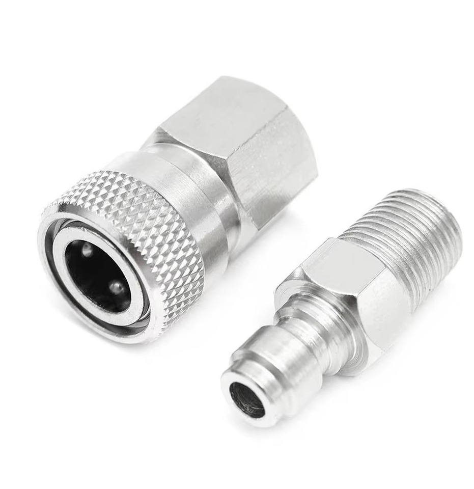
Long-term reliability in machined fittings does not come from one perfect part. It comes from the thousandth part matching the first one, and the part machined on a hot Friday afternoon matching the one cut on a cool Monday morning. That is where AI-corrected CNC machining and traditional methods part ways. Traditional machining relies on offline sampling, operator judgment, and compensation tables built from yesterday’s data. AI correction moves the compensation into the cutting cycle itself, using live signals to adjust coordinates, feeds, or tool paths before the deviation becomes a scrapped part or a slow leak in the field. The difference shows up most clearly in fittings where a few microns separate a seal from a weep, which is exactly the kind of work that soda machine adapters and scuba valve adapters demand.
Traditional reliability depends on catching drift after it has already happened
A conventional CNC process controls dimensions the same way a driver controls speed with only the rearview mirror. The part gets machined, pulled, measured on a CMM or a bench gauge, and the offset gets updated for the next run. If the machine has drifted within that sampling window, the drift is invisible until the next check. Thermal growth is the classic culprit. A spindle running at high RPM can heat past 55 degrees C, ball screws warm by several degrees during continuous positioning, and an uncontrolled ambient swing of only 5 degrees C can push a one-meter steel bed out by more than 55 microns. In a fitting held to plus or minus 5 microns, a 2 degree C shift is enough to breach the tolerance band.
The old manual response was to stop production every couple of hours, measure, and hand-update offsets. That trial-and-error loop typically costs 15 to 20 percent of overall equipment effectiveness and leaves a real risk of producing scrap between checks. The reliability problem is not that traditional machining cannot hit a tolerance. It is that the process only knows the tolerance was hit after the part is already off the machine.
AI correction closes the loop inside the cycle instead of after it
AI-corrected machining does not wait for a CMM report. Thermal sensors feed multi-point temperature data from spindle bearings, castings, ball screw nuts, and ambient air into a model trained on material expansion curves and finite element analysis. The controller then applies micro-adjustments to the coordinate system while the tool is still cutting. In one reported implementation, dimensional deviation moved from a range of 0.008 to 0.012 mm down to plus or minus 0.002 mm, and thermal scrap dropped by more than 85 percent.
That matters for long-term reliability because accuracy degradation is not a single event. A review of machine tool accuracy retention describes it as a permanent recession driven by wear, residual stress release, bolt creep, interface morphology changes, and thermal effects, with interface characteristics contributing roughly 90 percent of damping and ambient temperature driving about 75 percent of workpiece geometric errors. A process that corrects only at the start of a shift addresses the reversible part of the problem. A process that corrects continuously addresses the cumulative part.
| Reliability factor | Traditional CNC | AI-corrected CNC |
|---|---|---|
| Thermal drift response | Manual offset update every 2 hours, 15 to 20 percent OEE loss | Real-time coordinate compensation, continuous through the cycle |
| Typical dimensional spread | 0.008 to 0.012 mm without compensation | Around plus or minus 0.002 mm in reported cases |
| Scrap from thermal drift | Detected between sampling intervals | Largely avoided before the cut completes |
| Tool wear handling | Fixed parameters plus periodic offset changes | Predicted or adaptive parameter shifts based on live signals |
| Batch repeatability | Dependent on operator discipline and sampling frequency | Less sensitive to shift changes and unattended runs |
| Main residual weakness | Drift invisible until measurement | Model and sensor dependency, still needs validation cuts |
The fitting geometry that fails first is usually a seal surface
In soda machine adapters, the dimensions that decide whether a fitting lasts are not the outside profile. They are the O-ring groove depth, the bore diameter that receives the cylinder valve, and the surface finish on the sealing face. A groove cut a few microns too deep lowers squeeze, and a bore with the wrong Ra gives gas a path across the seal. Reports from adapter users describe the same sequence repeatedly: a connection that feels tight, then a slow CO2 loss, then a replacement washer that fixes it for a while and then stops fixing it.
Industry failure data points in the same direction. Roughly three quarters of adapter related failures begin with a sealing fault, often from aged or cracked O-rings and worn fitting interfaces. A Parker Hannifin failure report cited in adapter manufacturing guidance attributes about two thirds of seal problems in carbonation equipment to materials that cannot handle CO2 and moisture at the same time. Surface finish is part of that seal system. A ground surface can drop from 1.6 microns Ra to 0.4 microns Ra in a single pass, and finishing to Ra below 0.2 microns has been associated with fatigue life improvements of 2 to 5 times compared with conventionally machined surfaces in the 1.6 to 3.2 micron range.
Traditional machining can produce that finish. The reliability question is whether it produces it on part 1, part 400, and part 4000, after the tool has worn and the spindle has heat-soaked. AI correction is not a polishing operation. It is a way to keep the cutting conditions that produce the finish from drifting out from under the part.
Scuba valve adapters show what happens when tolerance and standard discipline separate
Scuba valve hardware raises the consequence of a dimensional miss because the pressure boundary is absolute. EN 144-1:2018 sets dimensional and tolerance requirements for cylinder valve inlet connections on respiratory protective devices, along with impact resistance and marking requirements. The same standard states that cylinder valves with a thread connection according to the standard shall not be used with an adapter between the valve and the cylinder, which is a reminder that an adapter is a design decision with standard consequences, not a universal fix.
Real failures in this space often trace back to exactly the kind of mismatch that continuous correction and standard discipline are meant to prevent. A documented case involved an imperial cylinder valve mated to a metric cylinder machined with an M25 x 2 parallel thread, a combination that should never have reached pressure. Another recurring issue in diving hardware is a valve face or adapter shoulder that does not seat because the mating surfaces are not machined to a common reference, leaving a gap that the seal cannot bridge. These are not abstract tolerance exercises. They are the difference between a valve that holds 300 bar and one that vents it.
A shop-floor case where the afternoon parts leaked and the morning parts did not
A fitting shop running soda machine adapters on a conventional vertical mill had a pattern that took weeks to pin down. Adapters machined in the first hours of the shift passed leak testing at a noticeably higher rate than adapters machined after lunch. The morning parts seated with a clean squeeze on the O-ring. The afternoon parts showed a slow bubble test failure at the same test pressure, and teardown found the groove depth had crept deeper as the spindle and the shop warmed through the day.
The shop’s first fix was to add a mid-day offset adjustment, which helped but did not eliminate the drift because the warm-up curve was not linear and changed with the weather. The second fix was a real-time compensation setup that tied spindle and ambient temperature to the Z-axis offset. The afternoon leak rate dropped to match the morning rate, not because the operator measured more often, but because the machine stopped relying on a measurement that arrived after the cut. The lesson was not that AI is smarter than a machinist. It was that a seal groove is a thermal part as much as a geometric one, and a sampling interval is a blind spot.
HXJ machines soda machine fittings and scuba valve adapters with the sealing interface treated as the controlling feature, which means the compensation strategy has to serve the groove depth and the bore finish, not just the outside diameter. That often means combining in-process correction with final inspection on the features that actually seal. AI-corrected machining improves the odds that the thousandth part behaves like the first. It does not replace the drawing, the standard, or the leak test, and anyone selling it as a substitute for those is overselling the tool.
Table of Contents
- Traditional reliability depends on catching drift after it has already happened
- AI correction closes the loop inside the cycle instead of after it
- The fitting geometry that fails first is usually a seal surface
- Scuba valve adapters show what happens when tolerance and standard discipline separate
- A shop-floor case where the afternoon parts leaked and the morning parts did not