 EN


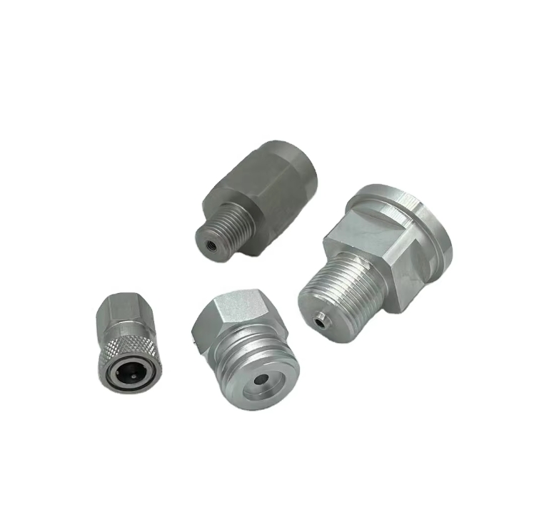
A CNC machine that cuts a perfect part on Monday morning and a leaky one on Thursday afternoon is not a machine with a bad operator. It is a machine whose tool center point has drifted while nobody was watching. Laser sensors and AI algorithms get paired in modern CNC correction for one blunt reason: the error has to be seen while it is happening, and the correction has to be decided before the cut finishes. A CMM report that arrives after the part is off the table tells you what went wrong. It does not save the part. For fittings where a few microns of seal groove depth decide whether a soda machine adapter holds CO2 or a scuba valve adapter holds 300 bar, that difference between after-the-fact and in-process is the whole game.
Thermal drift is the error source that sampling cannot catch
The biggest driver of dimensional drift in a running CNC is heat, and it does not announce itself. Frictional heat in ball screw feed drives expands the screw and pushes the tool center point off its commanded position, which is a major source of positioning error in high-speed machining. Spindle bearings warm at a different rate than the castings around them. Ambient temperature moves the whole frame. None of these effects are linear, and none of them pause while the operator walks over with a micrometer.
The traditional response is periodic measurement and offset adjustment. That loop works for slow processes with generous tolerances. It fails for fittings where a groove depth is held to a few microns and the thermal time constant is shorter than the sampling interval. The parts made between two checks are a blind spot, and those parts are the ones that show up later as a slow leak or a seal that never seated. Laser measurement and AI prediction do not make the machine thermally stable. They shrink the blind spot from hours to milliseconds.
Laser sensors turn the cutting zone into a measurement zone
A laser sensor mounted on or near the spindle does not need the part to be moved to a CMM room. It measures the tool, the workpiece surface, or a reference feature while the machine is still in a position to do something about the number it just read. In one published system for precision CNC, a four-quadrant photodetector paired with a back-propagation neural network reduced X-axis root-mean-square positioning error from 0.087 mm with a traditional centroid method to 0.012 mm, an 86.2 percent improvement, while the optical path and an adaptive Kalman filter handled noise and spot quality. Another on-machine measurement setup using a laser line triangulation sensor cut maximum machining error on a thin-walled surface from 0.022 mm to 0.011 mm, with the measurement pass taking about 90 seconds.
The sensor’s job is not to replace final inspection. It is to give the correction loop a live error signal instead of a historical one. A laser displacement sensor mounted on a CNC can track coordinate displacement and feed a compensation algorithm while the tool path is still active, which is the difference between correcting the next part and correcting the current one.
AI algorithms earn their place by predicting what the sensor will see next
A sensor tells you where the tool is now. An AI model tells you where it is heading. Thermal error in a ball screw or a spindle is a time-series problem with hysteresis, cross-coupling, and a warm-up curve that changes with the shop’s ambient conditions. Physics-based models capture the first-order behavior, but they get brittle when the machine has been running all day, the coolant temperature has crept up, and the tool wear is no longer in the range the model was tuned for.
That is where learned models come in. A deep reinforcement learning framework fused with a genetic algorithm for CNC turning reported a mean absolute error of 2.6 micrometers on aerospace-grade Ti-6Al-4V, an 86.3 percent compensation effectiveness, with a process capability index of 1.67. The same study was honest about the limits: compensation accuracy degrades once cutting parameters drift more than 30 percent beyond the training envelope, or when the workpiece material differs substantially from what the model learned on. That limitation is not a footnote. It is the reason AI correction is not a fire-and-forget upgrade. The model has to be fed, validated, and kept inside its domain.
The seal groove is where real-time correction pays for itself
In a soda machine adapter, the features that decide long-term reliability are not the external thread or the cosmetic profile. They are the O-ring groove depth, the bore that receives the cylinder valve, and the surface finish on the sealing face. Failure data from adapter maintenance points in the same direction: roughly three quarters of adapter related faults begin with a sealing problem, commonly an O-ring that has aged, flattened, or cracked, or a fitting interface that has worn enough to stop loading the seal. Those are not random material failures. They are often the downstream result of a groove that was cut a few microns deep or a bore finish that let the elastomer extrude.
A laser sensor can catch a groove depth drift on the current part. An AI model can predict that the drift is accelerating as the spindle heat-soaks. Neither one makes the O-ring better. What they do is keep the groove and the bore inside the window where the O-ring can do its job, on the first part and the four-thousandth part, not just on the sample that happened to be measured before lunch.
When the adapter standard and the machining tolerance disagree
Scuba valve adapters make the cost of a missed correction more obvious because the pressure boundary does not forgive a marginal fit. Documented mismatches in diving hardware show how quickly a thread that “looks close” becomes a sealing failure. An M25 valve thread can appear to engage a 3/4-inch NPSM cylinder neck, but it requires more force to tighten and will likely not seal correctly, pushing the operator into significant over-tightening that distorts the interface. Damaged 300 bar DIN valve outlets can prevent the valve from screwing all the way in to seat the O-ring, and chasing the threads is a temporary fix that removes material from a pressure boundary that was not designed to lose it.
These are the failure modes that a real-time correction strategy is meant to prevent at the source. If the thread flank, the sealing shoulder, or the O-ring groove is drifting during the cut, a laser reading plus a model correction keeps the geometry inside the standard instead of leaving it to a final gauge that either passes the part or scraps it. The AI does not know the standard. The process has to be built around the standard, with the correction loop serving the features the standard actually cares about.
Where a specialist fitting shop actually uses the loop
A fitting shop machining soda machine adapters had a pattern that took weeks to trace. Adapters cut in the first hours of the shift sealed cleanly at leak test. Adapters cut after the spindle had been running for several hours showed a higher bubble-test failure rate at the same test pressure, and teardown found the O-ring groove had crept deeper as the machine warmed through the day. Adding a mid-day offset adjustment helped, but the warm-up curve was not linear and moved with the weather. The shop moved to a laser measurement pass tied to a compensation model that tracked spindle and ambient temperature. The afternoon leak rate dropped to match the morning rate, not because the operator measured more often, but because the correction happened while the groove was still being cut.
HXJ machines soda machine fittings and scuba valve adapters with the sealing interface treated as the controlling feature, which means laser measurement and model-based correction are aimed at groove depth, bore diameter, and sealing-face finish rather than just the outside profile. The hardware is only as good as the error signal it receives. Laser sensors and AI algorithms are valuable in this work because they shorten the distance between a drift starting and a correction landing, and in fittings that seal at pressure, that distance is where reliability is won or lost.
Table of Contents
- Thermal drift is the error source that sampling cannot catch
- Laser sensors turn the cutting zone into a measurement zone
- AI algorithms earn their place by predicting what the sensor will see next
- The seal groove is where real-time correction pays for itself
- When the adapter standard and the machining tolerance disagree
- Where a specialist fitting shop actually uses the loop