 EN


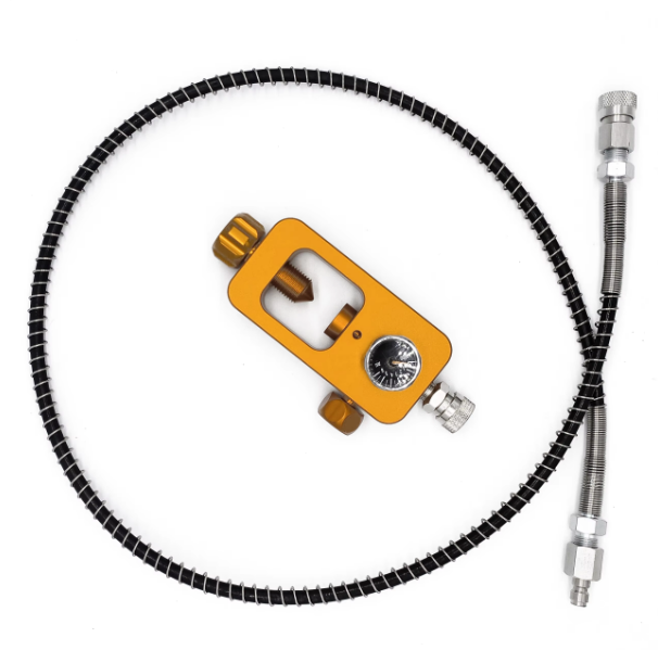
The 300 Bar Threshold: Where Standard Adapters Stop Being Standard
Refilling a scuba tank at 300 bar is a different beast from the routine 200 bar fill. The physics change. The margin for error shrinks. And the adapter sitting between the fill station and the cylinder valve becomes a critical safety component rather than just a convenient threaded piece of brass.
The DIN valve system, standardized under ISO 12209, specifies threaded outlet connections for cylinder working pressures up to 300 bar. But the 200 bar and 300 bar DIN fittings, while visually similar, are not interchangeable. A 200 bar first stage regulator will not seal properly in a 300 bar cylinder valve—and that's by design. The thread count difference (five turns for 232 bar versus seven for 300 bar) prevents accidental overpressurization of lower-rated equipment.
What Actually Happens When a 300 Bar Fill Goes Wrong
A facility in the Gulf region servicing commercial dive operations once reported an incident where a technician used a 200 bar-rated adapter on a 300 bar fill station. The adapter held for the first dozen fills. On the thirteenth, the O-ring extruded past the thread root at around 270 bar. The sudden depressurization sent the fill whip whipping across the fill bay. No one was hurt, but the adapter was recovered embedded in a concrete block wall three meters away.
That scenario plays out more often than the industry likes to admit. The force exerted on a 300 bar connection during filling is substantial. When a thread connection fails—whether from incorrect adapter specification, worn threads, or an improperly seated O-ring—the sudden release of pressure creates a shock wave that can do extensive damage. The valve itself becomes a projectile.
Thread Geometry: The Five-Turn vs. Seven-Turn Distinction
The mechanical difference between 200 bar and 300 bar DIN fittings comes down to thread engagement length. A 232 bar (commonly referred to as 200 bar) DIN valve has a thread with five turns. The 300 bar version uses seven turns and is slightly longer.
This isn't arbitrary. The additional thread engagement distributes the axial load from internal pressure across more surface area. At 300 bar, every square millimeter of the sealing interface carries a significant load. Fewer threads mean higher stress per thread—and a higher probability of galling, cross-threading, or outright failure.
A 300 bar DIN regulator will thread into a 200 bar valve, but a 200 bar regulator will not fully engage a 300 bar valve. Two or three threads will remain exposed on the regulator fitting. Some divers assume this is acceptable. It is not. That exposed thread is a visual indicator that the regulator is not designed for the pressure rating of the cylinder.
O-Ring Placement and the Sealing Surface Dilemma
DIN systems place the O-ring on the first stage regulator, not on the cylinder valve. This differs from the yoke system, where the O-ring sits on the valve itself. The O-ring in a DIN connection seals against a flat face inside the valve.
The sealing surface must be clean, free of scratches, and within tolerance. A single nick from a dropped cylinder or a misaligned thread start can compromise the seal. At 300 bar, that compromised seal becomes a leak path. The leak might be slow enough to go unnoticed during a visual inspection but fast enough to drain a full cylinder overnight.
Critical pre-fill checks for 300 bar DIN adapters:
Inspect the O-ring for cuts, flattening, or signs of extrusion.
Check the female threads in the valve for debris or damage.
Verify that the adapter or regulator threads engage fully—no more than one thread should remain visible.
Confirm the adapter's pressure rating matches the fill pressure.
The Real-World Performance Gap: Material and Manufacturing Matter
Not all 300 bar DIN adapters are created equal. The dimensional tolerances specified in ISO 12209 and DIN 477 are tight, but manufacturing variability exists. A poorly machined thread with a pitch error of just 0.05 mm can reduce effective thread engagement by an entire turn. At 300 bar, that lost engagement translates directly into reduced safety margin.
| Factor | 200 Bar DIN | 300 Bar DIN | Safety Implication |
|---|---|---|---|
| Thread turns | 5 | 7 | Longer engagement = better load distribution |
| Max working pressure | 232 bar | 300 bar | Overpressurization risk with mismatched components |
| O-ring location | Regulator first stage | Regulator first stage | Seal integrity depends on clean sealing face |
| Adapter compatibility | Fits 200 bar valves only | Fits both 200 and 300 bar valves | 300 bar regulator works on 200 bar valve; reverse is unsafe |
When an Adapter Isn't Just an Adapter
The distinction between a DIN-to-yoke adapter and a straight DIN adapter matters for 300 bar applications. A DIN-to-yoke adapter converts a DIN regulator to fit a yoke-type cylinder valve. But yoke valves are only rated for 200/232 bar cylinders. Using a DIN-to-yoke adapter on a 300 bar fill introduces a weak link—the yoke clamp wasn't designed for 300 bar service.
For 300 bar operation, stick with a straight DIN connection. If travel requires yoke compatibility, carry a separate yoke regulator or accept the limitation that the adapter is for 200 bar fills only.
HXJ manufactures DIN valve adapters with thread geometries verified against ISO 12209 and DIN 477 gauging standards, using inspection protocols that catch pitch and flank angle deviations before parts leave the floor.
Table of Contents
- The 300 Bar Threshold: Where Standard Adapters Stop Being Standard
- What Actually Happens When a 300 Bar Fill Goes Wrong
- Thread Geometry: The Five-Turn vs. Seven-Turn Distinction
- O-Ring Placement and the Sealing Surface Dilemma
- The Real-World Performance Gap: Material and Manufacturing Matter
- When an Adapter Isn't Just an Adapter